2.3
Basic characteristics and elements the CubeSat standard for small satellites
As mentioned above, the basic characteristics and elements of CubeSat satellites can be found in the specification contained in [15]. This specification describes the areas of design and testing of CubeSat picosatellites that can also be applied to small satellites of nano or femto category.
This document also describes the design requirements for a launcher in orbit for at least three small CubeSat satellites. This device is referred to as P-POD (Poly-Pico Satellite Orbital Deployer). It is a spring-loaded launching mechanism that launches a satellite into space along the rail. There must be compatibility for releasing the individual modules of 1U to 12U.
An example of the construction of the deployment device is shown in Figure 38.
©
For licensing reasons, this image cannot be directly incorporated into the material. Click HERE to see the image.
Fig. 38. CubeSat satellite deployment device
The structure is designed so that it can be modularly extended for more modules, as shown in Figure 39.
©
For licensing reasons, this image cannot be directly incorporated into the material. Click HERE to see the image.
Fig. 39. The deployment module of 4 CubeSat 12U
The CubeSat's standard specifications describe requirements for:
- Mechanical elements – for example, the CubeSat will use a coordinate system for the appropriate size as defined in Appendix B. The CubeSat coordinate system must match the P-POD coordinate system. The origin of the CubeSat coordinate system is located in the geometric center of the CubeSat.
- Electrical components – for example, the CubeSat power system must be in a power-off state to prevent spontaneous activation of the CubeSat function while being integrated with the P-POD from handover to a completed orbit location. CubeSat functionality includes variety of subsystems such as Command and Data Handling (C&DH), radio communication, Attitude Determine and Control (ADC), a releasing mechanism. CubeSat power systems include all batteries, photovoltaic (solar) panels, and fixed (button cell) batteries.
- Operating elements – for example, that operators obtain and provide documentation of proper licenses for the use of radio frequencies, CubeSat will comply with its licensing agreements and restrictions of own State. The design and execution of the CubeSats mission shall be in accordance with NASA's requirements for orbital debris reduction, as set out in NPR 8715.6.
It also contains the qualification and acceptance requirements for testing before handing over the launcher for launching small satellites. These consist of random vibration tests, thermal and vacuum climate tests, shock tests, and a visual inspection.
An example of the construction of the CubeSat 1U is shown in Figure 40. It is a test element which can be purchased for example from Pumpkin Inc. (http://www.cubesatkit.com/).
©
For licensing reasons, this image cannot be directly incorporated into the material. Click HERE to see the image.
Fig. 40. The skeleton of CubeSat 1U (Pumpkin Inc.)
The company offers additional core components for satellite construction, development, and testing of internal and communication systems and to support payload construction as shown in Figure 41. (http://www.cubesatkit.com/content/overview.html).
©
For licensing reasons, this image cannot be directly incorporated into the material. Click HERE to see the image.
Fig. 41. The basic set CubeSat 1U and development components which can be purchased Pumpkin, Inc.
The assembly in Figure 41 includes a skeleton, flight module with programmable adapter, development board, programmer and debugger, software, cables, and power supply. A list of this company's production missions is available at http://www.cubesatkit.com/content/space.html.
The testing process is very important because it has a fundamental impact on the overall outcome of the mission. Any faults or design errors can be eliminated in time before the start of launching a rocket.
Possibilities for the elimination of construction errors or other defects in the orbit are very limited, if not impossible. For example, insufficient power supply capacity or the power of rechargeable photovoltaic panels cannot be fully corrected during a mission. Maximum power consumption can be reduced by reducing the frequency of communication, correction of the orbit, finish experiments and the like.
The CubeSat standard also includes a methodology for the course and content of the testbed which is shown in simplified form in Figure 42.
+
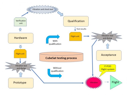
Fig. 42. CubeSat testing process
Test procedure, according to Figure 42, has two paths. This depends on whether the CubeSat satellite is first installed with a validation flight unit of the satellite or is built directly with a flight unit.
The first path is mostly used when purchased and tested components are not used. Although it is more expensive but they have to weigh the risks in the light of financial implications in the event of mission failure or in causing the space accident to deal with damages.
The CubeSat standard development did not stop, as well as advanced technology for building the satellites and the availability of kits from a variety of manufacturers (see for example https://blog.bliley.com/top-20-best-cubesat-satellite-manufacturers).
Thanks to the worldwide CubeSat community, all documents related to construction, fabrication, and operation are freely available on the Internet. Therefore, when planning a mission, it is always necessary to study them in their current version.
2.3
Technical tools for the planning, development, simulation, and operation of small satellites CubeSat
Project planning and development missions with small satellites CubeSat can significantly streamline the use of a partial or complex set of software simulation tools. These simulators are designed for the testbed of project development.
The simulation's objective is to define the parameters and requirements for small satellites before deciding on the hardware and software. This is also with regard to the provision of planned experiments and payload applications in the simulation of the course from the start of the mission, orbit operation until the end of the mission. The simulation takes into account the mission’s entire life cycle.
For example, during simulations, it can be shown that the proposed power capacity of the power supplies is insufficient due to the operating conditions of satellite systems in orbit. Based on this fact, the power supplies will be strengthened, or the thermal regime on the satellite will be adjusted. Ultimately it may lead to the fact that this will increase the module used CubeSat because it will need to add additional batteries. Such a simulation can substantially reduce the risk of mission failure and contribute to optimizing the overall financial cost of its implementation.
One product that is particularly useful in educational projects is the NASA Operation Simulator for Small Satellites - NOS3 [17]. It is primarily designed for easy integration to flight software developed with the NASA Core Flight System (cFS). The NOS3 simulator was created by NASA's Independent Verification and Test Capability team for CubeSat 3U named Simulation-to-Flight (STF-1).
The NOS3 simulator software is freely available for download on the Internet (http://www.stf1.com/NOS3Website/Nos3MainTab.html). On this page, one can also obtain complete documentation usable for further development of their own simulation applications.
This simulation software is open-source and uses Linux libraries and executables. Simulations are based on current hardware models used by CubeSat small satellites. However, even the hardware model implemented from commercially available components and components are not necessarily the production of space industry. It can also run on the Microsoft Windows 10.
The simulation takes place on a virtual machine “Unbut Linux virtual machine” with communication via a graphical user interface (GUI). It is running on any sufficiently equipped PC (especially with RAM more than 16 GB). In this environment, the simulation is assembled, controlled, and the results analyzed.
The NOS3 simulator can be used for the following tasks:
- the initial flight software design (FSW) through real inputs,
- the FSW testing at each stage of development and modification,
- the integration of FSW components for payload application design,
- the mission planning related to the verification of its components and the possibility of analyzing simulation results (e.g. analysis of the satellite's power supply system in conjunction with the planned payload).
The basic components of the NOS3 simulator are:
Oracle VirtualBox and Vagrant
The Oracle VirtualBox is an open-source software for creating and running virtual machines.
The Vagrant is an open-source software that can be used to script and create the Oracle VirtualBox machines, including installing packages, creating users, manipulating files and directories, etc.
NOS3 Engine
The NASA NOS3 Engine is a developed solution for simulating hardware buses as software-only buses. This component provides connectivity between flight software and simulated CubeSat hardware component models.
Simulated Hardware Components
A set of simulated hardware components (their software models) that connect ones to the NOS3 Engine and provide hardware input and output to flight software.
Software 42
Some hardware components require dynamic data in the environment in which small satellite components and systems operate. Software 42 is an open-source visualization and simulation tool for spacecraft and orbit dynamics developed by NASA's Goddard Space Flight Center (GSFC). It is used to provide dynamic environmental (ambient) data on a small satellite (for example, magnetic field data, orbit positions as inputs to a magnetometer simulator or GPS).
Flight software cFS
NASA's Core Flight Software (cFS) is used as the base system, which is designed on NASA's STF-1 flight software.
COSMOS
COSMOS is an open-source ground system software developed by Ball Aerospace for the ground station control and the flight software management.
OIPP
OOIP (Orbit, In view and Power Planning) is a planning tool that uses current sets of two-line elements (TLEs) to describe the orbital motion (around the Earth) from the Internet, to project small satellite times to display at a ground station, and to predict solar eclipses and sunlight times
COSMOS File Creator (CFC)
CFC allows generating commands and telemetry files from FSW flight software to be analyzed.
The NOS3 software architecture is shown in Figure 43.
+
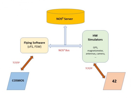
Fig. 43. The NOS3 software architecture
Individual components of the software architecture in Linux are in simplified form shown in Figure. 44.
+
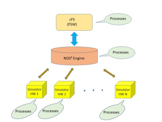
Fig. 44. NOS3 architecture in the Linux operation software
The NOS3 simulator development continues. It is freely accessible through its source code. Therefore, this software can be developed according to the specific needs of the user. Thus developed models of hardware or interfaces can be included in the software simulation systems to processes of the NOS3.
Currently, the first version of NOS3 [18] is available the simulation software for the magnetometer Honeywell HMC58453 (FSW source code for development), electric power system Clydesoace Gen III (analysis of power system and control software switches), GPS from Novatel (FSW source code GPS development and command) and ArduCam Mini OV2640 SPI / I2C camera (FSW source code for development and exchange of extensive packets of data).
An example of a complete NOS3 user interface with its components is shown in Figure 45 [17].
©
For licensing reasons, this image cannot be directly incorporated into the material. Click HERE to see the image.
Fig. 45. Demonstration of the NOS3 simulator user interface in the Linux operating system
Simulator development continues with the participation of the CubeSat´s community. It includes simulation models of 3-axis gyro hardware, temperature sensors, UHF radio transmitter, and receiver, and the user interfaces for visualization and the integration with software COSMOS and ITOS with the software 42.
A key aspect of the NOS3's use and benefits of ability is to simulate a mission in the design and planning phase for the entire life cycle (construction, testing, launch, operation, and termination) with a minimal cost. The results can be used for any hardware and software changes of small satellite systems and its payload even before it comes to the actual construction and subsequent testing of components and the flight model of a small satellite.
Using this simulator can also refine estimates of individual items in the financial budget for the construction phase of the small satellite mission, its payload, operations, and termination. These create good preconditions for the success of the mission.
Moreover, thanks to this simulator, the teaching process can be significantly streamlined at the level of secondary schools. In the beginning, there isn’t a need for expensive equipment for theoretical and practical instruction. A personal computer or notebook with at least 16 GB of RAM is sufficient. The Linux operation system software and its libraries are free to download and use.
More detailed information on the described simulator and its use can be found in the reference source [17] and [18].
2.4
Examples of projects based on the CubeSat standard
Many examples of projects based on the standard of small CubeSat satellites, their constructions, and equipment were discussed in previous chapters. The selection of examples of projects based on the use of the CubeSat standard is not an easy matter due to the considerable number of ongoing or planned missions at schools and a range of large projects, such as the OneWeb.
With regard to the focus of this material for secondary schools, we will briefly describe the basic characteristics of two typical projects that document the education potential of small satellites using the CubeSat standard. A detailed description of individual projects that are part of the project QB 50 is beyond the scope of this document and can be found in the following references.
The first is the European project QB 50. It has a significant impact on the introduction and development of technology of small satellites in the university (and by extension to secondary schools) and spin-off businesses (type of small business for the transfer of scientific research into commercial use). The European Commission supports this project under the 7th EU Framework for Research and Technological Development for 2014-2020.
The objectives of QB 50 are directed to the following four areas:
- scientific research,
- facilitating access to space,
- a platform for technological activities in orbit,
- education.
The aim was to create an international network with a constellation of up to 50 small CubeSat satellites of the 2U or 3U module (nanosatellites), a three-year life cycle, and a scientific payload for in-situ multipoint measurements in lower thermosphere. The Institute von Karman (Rhode-Saint-Genèse, Belgium) manages this EU project. There are 23 major universities from 15 countries in the project consortium.
QB50 project mission shows the possibility of development of small satellites CubeSat, which is to perform scientific research in the largely unexplored lower thermosphere at altitudes from 200 km to 380 km created by university teams worldwide.
Multipoint measurements, using the QB50, complement current research via launching and tracking audio rocket by Earth observation satellites. OB 50 results should contribute to the development of more accurate models in the lower layers of the thermosphere.
Three different types of sensors are used for these measurements. Each is a part of a set of three sets of scientific experiments. It uses sensors as an ion neutral mass spectrometer (INMS) which is the first part of the magnetic-flux Φ-probe experiment (FIPEX) as part of the multiple secondary set and the Langmuir probe (m-NLP) as part of the third set. In each of them is a measuring device for measuring the temperature using a resistance temperature detector (RTD), thermistors or bimetal sensors (TH).
Besides the scientific research, there is a part of the development of the special deployment (bus) interface called QuadPack. It places small satellites in orbit. This system has been validated in orbit and serves as a standardized platform for launchers of small satellites into space.
The QuadPack is a structurally multifunctional device with simple and flexible interfaces and configurations for CubeSat satellites and launchers. During launch, CubeSat satellites are fully enclosed in this QuadPack and are released into space under the command of the launch device on the orbit vehicle.
Example design of the deployment device QuadPack manufactured by ISIS CubeSat project QB 50 is in Figure 46 (https://www.isispace.nl/product/quadpack-cubesat-deployer/).
©
For licensing reasons, this image cannot be directly incorporated into the material. Click HERE to see the image.
Fig. 46. Design of the ISIS QuadPack deployment device
The development of these QuadPacks is a means of sustainably supporting access to space. It is proven (qualified) for a large number of CubeSat modules, and is capable of flying on many repeated launches of small satellite missions.
The launch of CubeSat satellites is mainly used by the international space station ISS. They are transported by rocket Atlas V (California). They also use vehicles PSLV (Polar Sun Launch Vehicle) carried into orbit by carrier rocket the Indian Space Research Organization (ISRO).
Another goal of the QB50 project is to serve as a platform for demonstrating technology. The part of the QB50 CubeSat payload, which does not include sensors designed for science, is primarily technology intended for use in space. Two of the CubeSat, QARMAN and InflateSail, are part of the consortium QB50 and demonstrate the purpose and mission of the project.
In the area of education, mission QB50 challenges universities to cooperate and participate in the building and to send small satellites into space. Under this call, QB50 selected several projects that have been designed and manufactured by a large number of young engineers. These projects are supervised by experienced staff at universities and managed by the QB50 project.
The ground segment for the QB50 consists of 50 ground amateur stations, a central DPAC (Data Processing and Archiving) server for TLE data, WOD (Whole Orbit Data), data collection from scientific experiments, and data archiving. For radio communication, amateur bands on wavelengths 2 m (145 MHz), 70 cm (435 MHz) and 6 cm (1.23 GHz) with digital modulation mostly GMSK (Gaussian modulation with minimal stroke used in GSM mobile networks) with transmission speeds up to 9600 bit / sec are used.
Tracking programs such as the Orbitron or the Gpredict make it possible to track the movement of individual satellites on the Internet. SDR receivers or Internet decoders (if provided by the project) can also receive live signals and decode transmitted data from tracked satellite. This is good study and educational material for those interested in small satellites.
The benefit of the QB50 is that in addition to theoretical knowledge, engineers also gain practical experience in satellite construction, testing, and operation. Students can learn about more than the theory of space, and leave their universities with practical experience. Moreover, it shows that the mission QB50 opened the door to today's secondary school projects and small interest groups or spin-off of various start-up enterprises established with the support of universities.
Currently, 48 missions of this project have been carried out, and others are planned. One of them is the project of the first Czech CubeSat nanosatellite. It will be described in more detail in the following chapter 2.5.
Information on the missions' sub-projects included in the QB 50 project and their current status can be found at https://www.qb50.eu/index-2.html, at https://upload.qb50.eu/ and many other resources related to specific QB50 subprojects. This project holds a series of annual conferences and seminars.
The second example of the mission project illustrates the enormous potential that is in small satellite technology and what opportunities are open to all those interested in space for their future professional career. It also demonstrates that small satellites allow access to and use of space, previously reserved only for large government space agencies or the first generation space industry corporations.
Above mentioned facts are confirmed by the project realized in the American elementary school St. Thomas More Cathedral School in Arlington, Virginia at 2014-2017 (https://www.nasa.gov/feature/first-cubesat-built-by-an-elementary-school-deployed-into-space). The goal was to send a CubeSat satellite 1U module named STM Sat-1. This elementary school mission project was realized as the first in the world.
The objective of the mission was to enable students to obtain theoretical knowledge and practical skills related to the operation of small satellites with payload for the Earth´s photography and image transmission and processing at their own ground station and other cooperating ground stations in the US and worldwide.
Joe Pellegrini (NASA Goarde Space Flight Center) led the project and involved 400 school pupils. J. Pellegrini acted as a mentor in all phases of the mission development from assembling a small satellite, testing, integrating, and launching one.
Throughout each phase, school pupils had the opportunity to participate in the implementation of this mission, under his leadership. In doing so, they learned a lot of electronic skills, such as soldering components, using antistatic component protection and handling soft components.
Two stratospheric balloon flights were used to test the design of the small satellite hardware prior to the construction of STMSat-1. The pupils built a ground station. During these years, they trained the operation in amateur bands and simulated radio communication with the upcoming small satellite.
STMSat-1 had an on-board camera for the Earth´s observation, an amateur radio transceiver, power supplies, on-board computer, antenna, a plate with mission team signatures, and a cross consecrated by Pope Francis.
The group was successful in securing theNASA CubeSat Launch Initiative along with 16 other organizations to launch the small satellite.
STMSat-1 was carried aboard the orbital ATK Cygnus spacecraft to the ISS on the 6th of December, 2015. The NanoRacks CubeSat Deployer (NRCSD) was used at orbit in altitude 402 km on the16th of May, 2016. After about 30 minutes, the internal systems were activated and a radio connection to the ground station was established.
Figure 47 shows STMSat-1 in orbit (http://www.canadensys.com/canadian-school-join-worlds-first-elementary-school-space-mission/)
©
For licensing reasons, this image cannot be directly incorporated into the material. Click HERE to see the image.
Fig. 47.The first school satellite STMSat-1 in orbit
Scanned images from the on-board camera and encoded by the amateur slow-camera system (SSTV) were to be transmitted via a Robot36 frequency modulation device at 437.800 MHz to ground stations. Unfortunately, this part of the mission could not be completed. Although the STM-1 is still in orbit, no image has been received at the ground stations.
Nevertheless, this pioneering school mission is considered as success. It has enabled many pupils of this school to pursue a number of space-related technical disciplines, and had also been a great inspiration for many other school and university CubeSat mission projects. At the same time encouraged to find support from both entities providing launching and deployment of CubeSat satellites into orbit and the new space industry for the manufacturing of small satellite kits and other necessary components. Last but not least, it also contributed to the development of the CubeSat standard.
2.5
The first Czech satellite CubeSat - VZLUSAT-1
The previous chapter described two examples of small satellite missions based on the CubeSat standard.
The Czech Republic is not left behind in the field of launching small satellites into space. On June 23, 2017, the Indian space rocket PSLV-C38 launched the first Czech nanosatellite VZLUSAT-1 based on the CubeSat standard [18].
The VZLUSAT-1 nanosatellite mission is part of the previously described QB50 project. Therefore, one part of its payload is a thermosphere research facility within the FIPEX experiment. Furthermore, there are other facilities for scientific and technological experiments. These are used to verify (qualification) products and technologies LEO orbits. Their location and construction of the nanosatellite are shown in Figure 48 [18].
©
For licensing reasons, this image cannot be directly incorporated into the material. Click HERE to see the image.
Fig. 48. Construction of VZLUSAT-1 and individual components location its payload
The VZLUSAT-1 CubeSat nanosatellite was developed at the Research and Testing Institute of Aerospace Engineering in Prague (VZLU) in a consortium consisting of the University of West Bohemia in Pilsen, FEE CTU in Prague, and technology companies Rigaku, 5M, HVM Plasma, TTS and IST. The development has been carried out since 2009 as part of the first Pilsen Cube project [19].
The basic parameters of VZLUSAT-1 are:
- CubeSat 2U-weight 2 kg, dimensions 10 x 10 x 20 cm in starting of launch configuration and 10 x 10 x 35 cm in deployed form (X-ray telescope and tilting solar photovoltaic panels) in orbit,
- registration in the NORAD system under number 427090,
- polar orbit with an inclination of 98˚ SSO (Sun Synchronous Orbit) at the altitude 510 km-520 km, average orbital duration 95 minutes,
- radio communication with a power of 1 W,
- a radio beacon – two states 600 Hz audio signal, carrier FM modulation at 437.240 MHz, transmissions a message with the name and status telemetry parameters of satellite systems (OBC WOD) with a period 60 sec.
- data transmission from experiments in the CubeSat packet protocol with MSK modulation (minimum frequency shift keying) on 437.240 MHz carrier frequency using the Gomspace NanoCom U482C SDR transmitter,
- an on-board computer (OBC) - the hardware uses LEON3FT processor cores and controlled I2C serial buses. OBC and flight software include FreeRTOS operating system, CubeSat Space Protocol (CSP), I2C control and payload application software.
The primary ground station is located on the roof of the Faculty of Electrical Engineering of the University of West Bohemia in Pilsen. Several cooperating secondary ground stations within the QB50 project receives the transmitted data.
The location of the ground station in Pilsen enables active communication and monitoring in the range of 5 minutes to 11 minutes with a 95 minutes orbit cycle period depending on the trajectory of the VZLUSAT-1 nanosatellite.
The ground station is equipped with a rotating azimuth and an elevation antenna system with a YAGI antenna (14.1 dBi gain) for the 70 cm waveband (UHF), an ICOM IC 910H amateur radio transmitter and receiver with 510 W power, a computer with flight management software VZLUSAT-1. These components enable the processing of received data and for connection to the LAN network for connection of cooperating subjects.
All radio communications, tracking, and other information on this project are publicly available on the website of the mission VZLUSAT-1 (https://www.pilsencube.zcu.cz/vzlusat1/).
The payload of VZLUSAT-1 consists of the following experiments and devices:
- X-ray telescope with optical particle detector TIMEPIX for measuring of ionizing radiation of the Sun and for measuring of the spectrum radiation around the Earth (scientific experiment) as a part of the FIPEX project within QB 50.
- A device for measuring shielding properties of the composite material (technological experiments). The use of these materials is expected for long-term crew´s flights and construction of objects inhabited by people on other planets (Moon, Mars).
- The corner reflector for accurate laser distance measurements to a small satellite.
Although the VZLUSAT-1 mission plan has a life cycle of one year, the satellite is active, and experiments continue in 2019. This is a very valuable and excellent result compared to many similar missions. Student involvement contributed to education at the Faculty of Electrical Engineering of the University of the West Bohemia in Pilsen.
The obtained results and knowledge contributed significantly to the solution of the FIPEX project within the QB50. Results of technology experiments are also a contribution and inspiration for other small satellite mission projects.
The success of the project mission VZLUSAT-1 is a result of good planning and project management, appropriate selection, and completion of tests of individual components and the whole nanosatellites and about top team´s erudition of this consortium.
Another Czech 1U CubeSat nanosatellite is LUCKY 7 realized by Czech association Sky Fox Labs. s.r.o. (https://www.lucky7satellite.org/). Its weight is 1.5 kg and dimensions are 112.0 x 112.0 x 113.5 mm. The satellite was launched on Friday, July 5, 2019 as a part of the Meteor-M 2-2 meteorological mission, along with 31 other small satellites.
Lucky-7 is based on the unrealized the CzechTechSat-1 project. Its payload are technology experiments for researching of Aurora using a VGA camera, and measuring cosmic rays using two sensors ranging from 0.3 to 3.0 MeV and from 0.3 to 10.0 MeV.